
Servercore Network Infrastructure
Automated networks with a capacity of 100 Mb/s combining your projects into a single infrastructure. Organization of connectivity with on-premise solutions and other network resources. Independent management of networks through a single panel. DDoS protection at L3—L4 level.

Why Choose Our Network Infrastructure?



Servercore is Stable, Simple, and Offers Local Infrastructure
Request a consultationIaaS и PaaS
Availability zones in Kenya, Uzbekistan, and Kazakhstan
IAM service for managing authorization and access levels
SLA up to 100%
Compliance with GDPR and DPA 2019
PCI DSS
Free migration
Billing in Kenyan shillings
Payment by MPesa or bank transfer
24/7
Choose the Region Where You Want to Deploy Your Service

-
 Dedicated Servers
-
 Cloud Servers
-
 Cloud Databases
-
 Managed Kubernetes
-
Dedicated Servers
-
Cloud Servers
-
Cloud Databases
-
Managed Kubernetes

-
Dedicated Servers
-
Cloud Servers
-
Cloud Databases
-
Managed Kubernetes
-
Dedicated Servers
-
Cloud Servers
-
S3
-
Managed Kubernetes
-
Dedicated Servers
-
Cloud Servers
-
Cloud Databases
-
Managed Kubernetes
Tier III data center in Nairobi
Compliance with global and local security standards
Five levels of client data protection
Types of our networks and their design
Servercore customers can work with three types of networks: the Internet, the local area network (LAN), and the private network of the global router. These networks are isolated from each other: the operation of one network does not affect the operation of the other. LAN allows to combine servers within a single pool directly through a high-speed L2 connection.
In the Internet access network, switches, links between them, access routers in projects, links between them and edge switch routers are reserved based on the N+1 scheme.
The components of the network differ depending on which server is used: cloud or physical.
Network infrastructure levels:
1. Access Switches
Provide physical access to the network for client servers.
2. Aggregation Switches
Provide communication between access switches, allowing servers to communicate with each other. Links between the first and second level are reserved.
3. Edge Switch Routers
Connect to several independent telecom operators in each region through external channels.
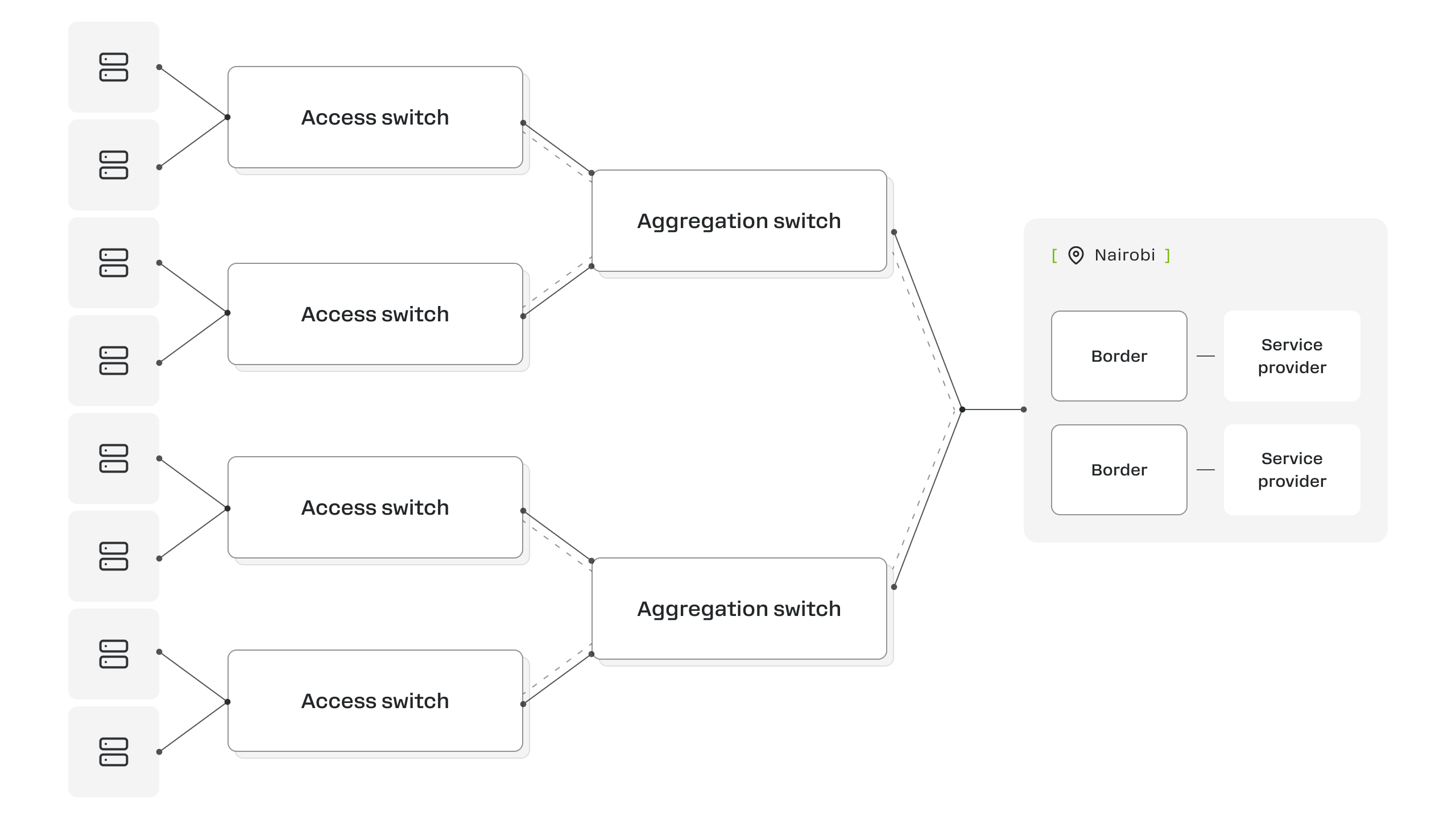
In the cloud network, we use the classic CLOS topology.
Network infrastructure levels:
1. Leaf switches
Installed in server racks where the physical nodes of the cloud are located and connect them to the network. Each physical node of the cloud is connected by at least two network interfaces to different leaf switches to ensure fault tolerance.
2. Spine switches
Connect various leaf switches to each other and enable physical nodes of the cloud connected to different leaf switches to exchange traffic. All connections between leaf and spine switches are reserved. Having these two network layers means that each leaf switch is connected to at least two different spine switches, with at least one connection to each spine one. Каждый leaf-коммутатор подключен минимум к двум разным spine-коммутаторам.
3. Edge Switch Routers
Connect to several independent telecom operators in each region through external channels.
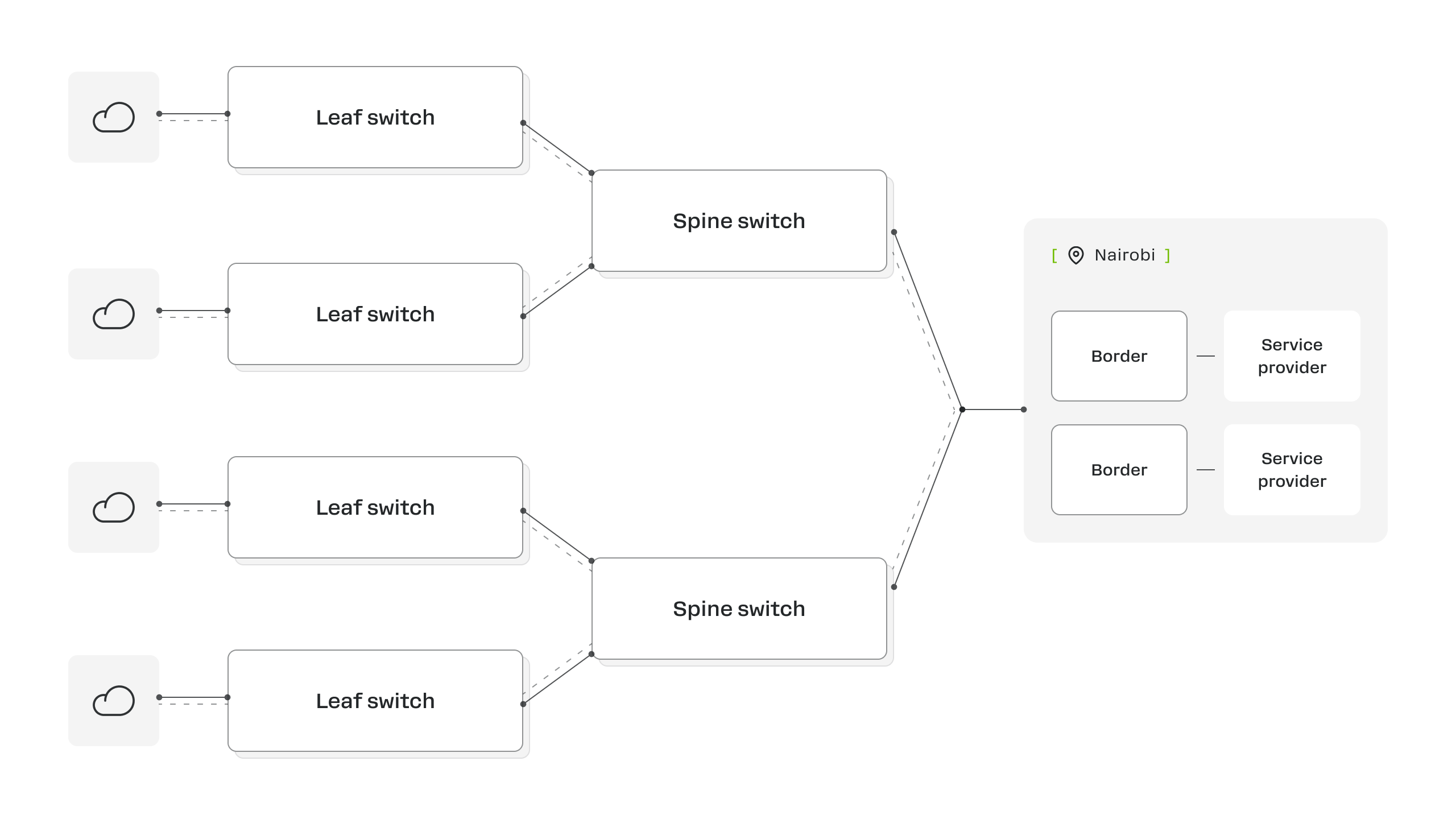
All connections with major operators are organized through ports. If it is necessary to change the port or network of the operator for some of the Internet traffic, this can be done manually for each edge switch router and connected providers. Typically, such changes occur unnoticed by the client servers and services.
Providers may have their own additional routing policies that affect further traffic to the Internet. The user can check the external route through the networks of operators to the desired resource, but cannot independently select a specific provider.
It is possible to change the operator. This option is available after connecting a separate service and if a user router is available.
Organizes network connectivity between physical and cloud infrastructure and creates an isolated private network within one or between several data centers.
— High security
— Isolation of client networks from each other
— N+1 redundancy of all network devices
— Connecting to local project networks via virtual routers
The global router network connects to project-specific local networks via virtual routers configured across multiple physical routers. This enables the creation of a unified distributed client global router.
This router merges various segments of client local networks into a single isolated network. Within this network, IP subnets are assigned to each segment and traffic is routed.
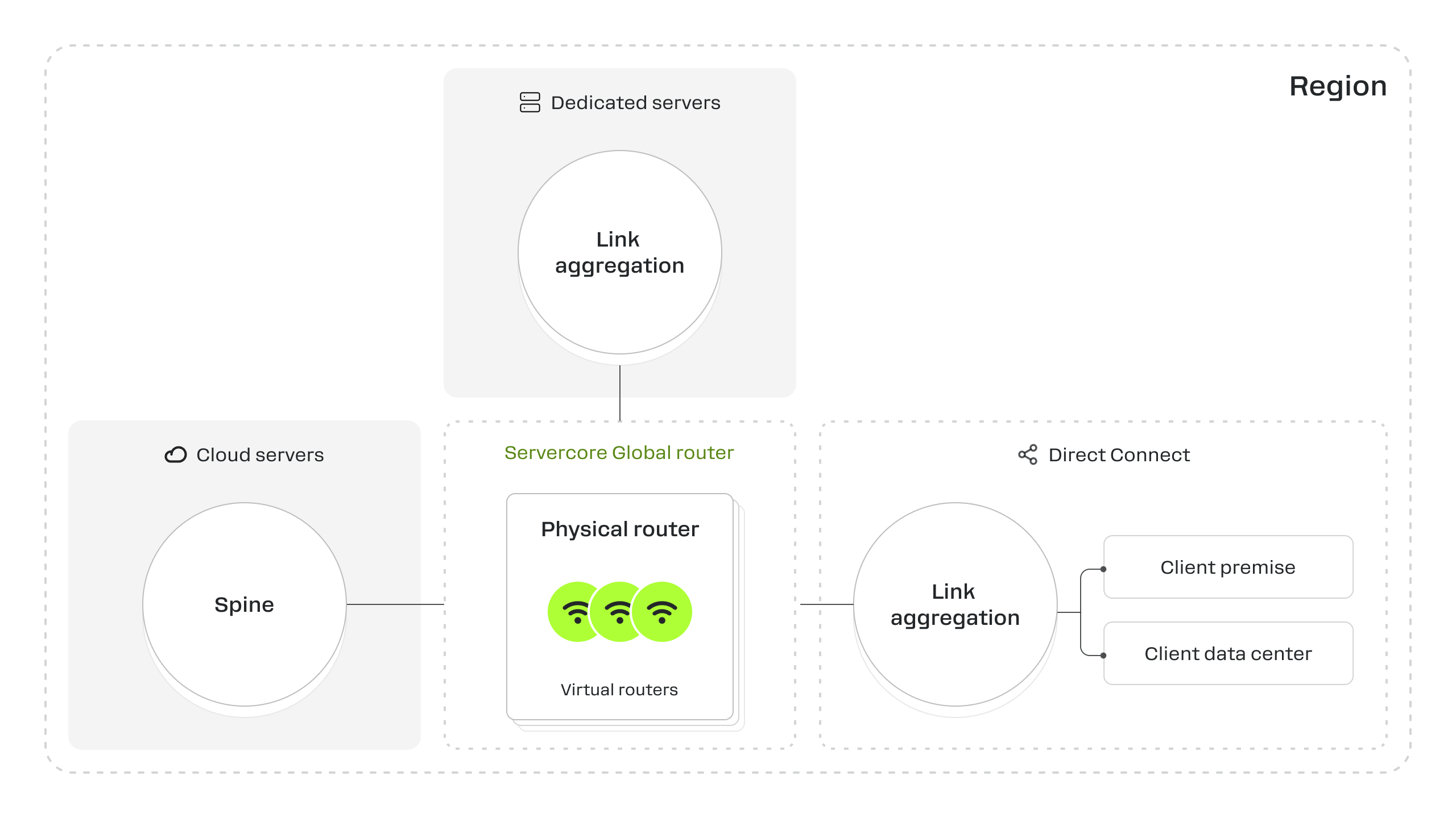
Establishing connectivity among products
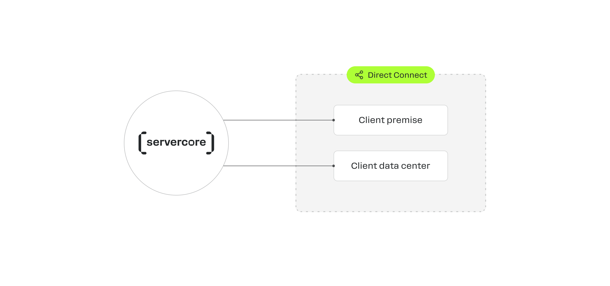
Establishes a dedicated network connection between Servercore infrastructure and the client’s on-premise infrastructure.
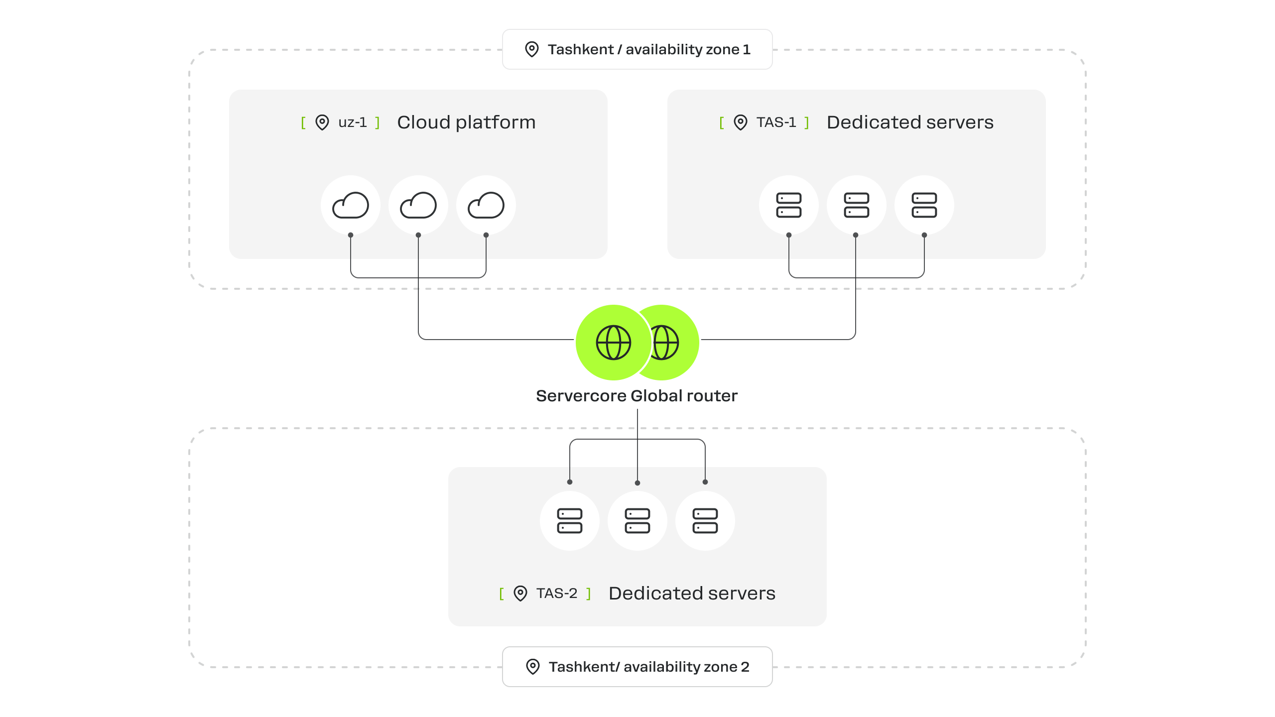
The Servercore global router can link cloud and dedicated servers both within a single region and across different regions.
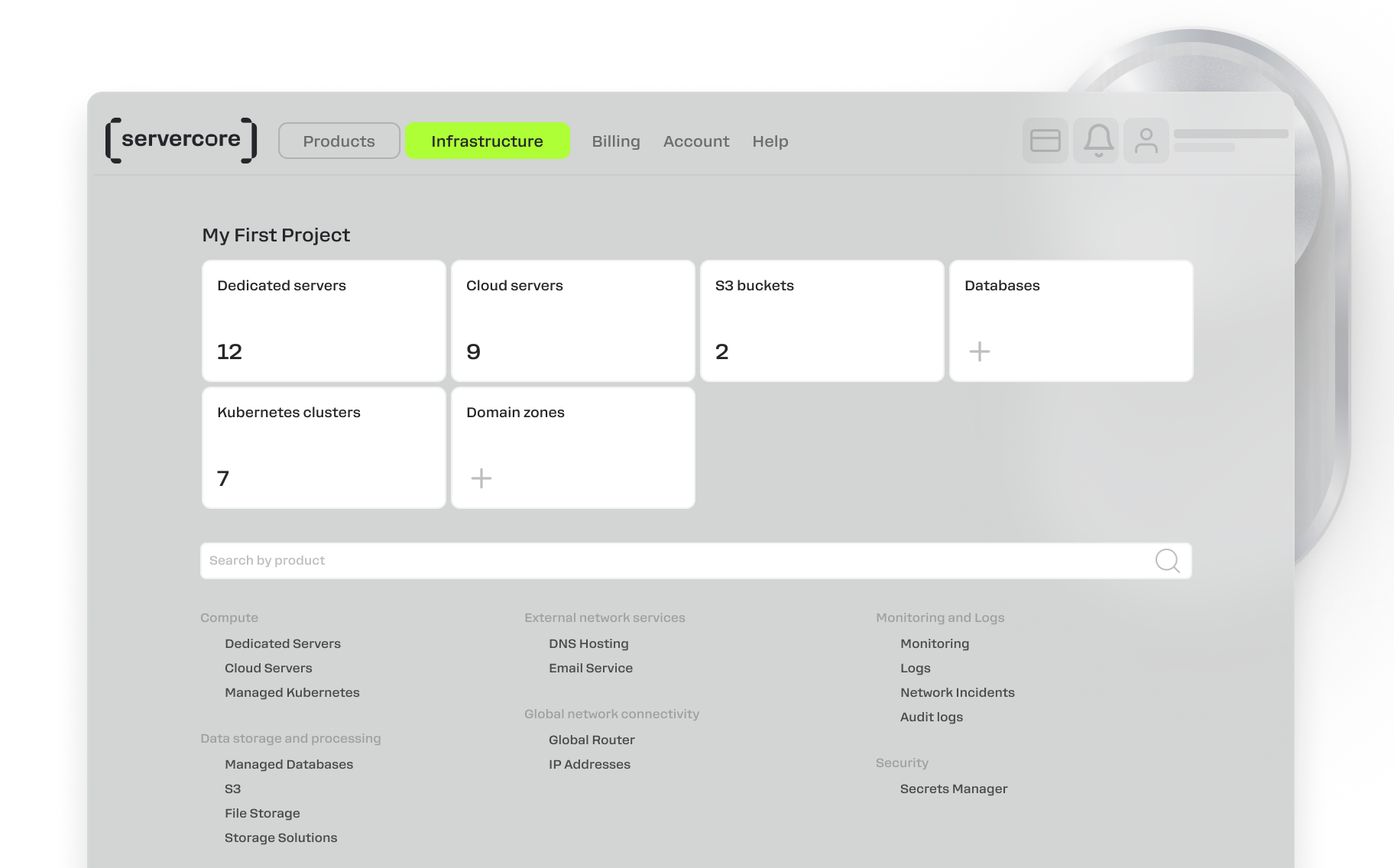
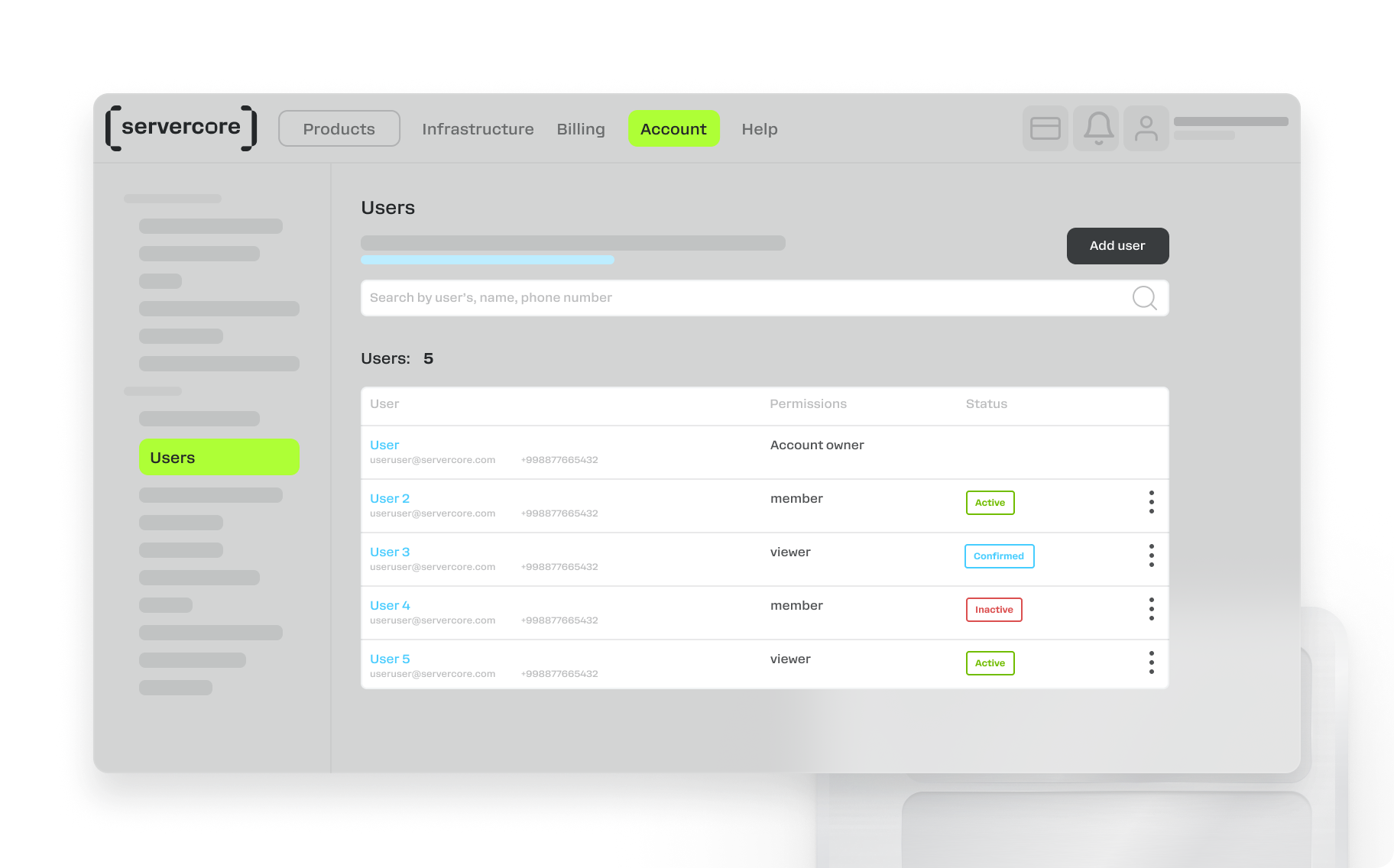
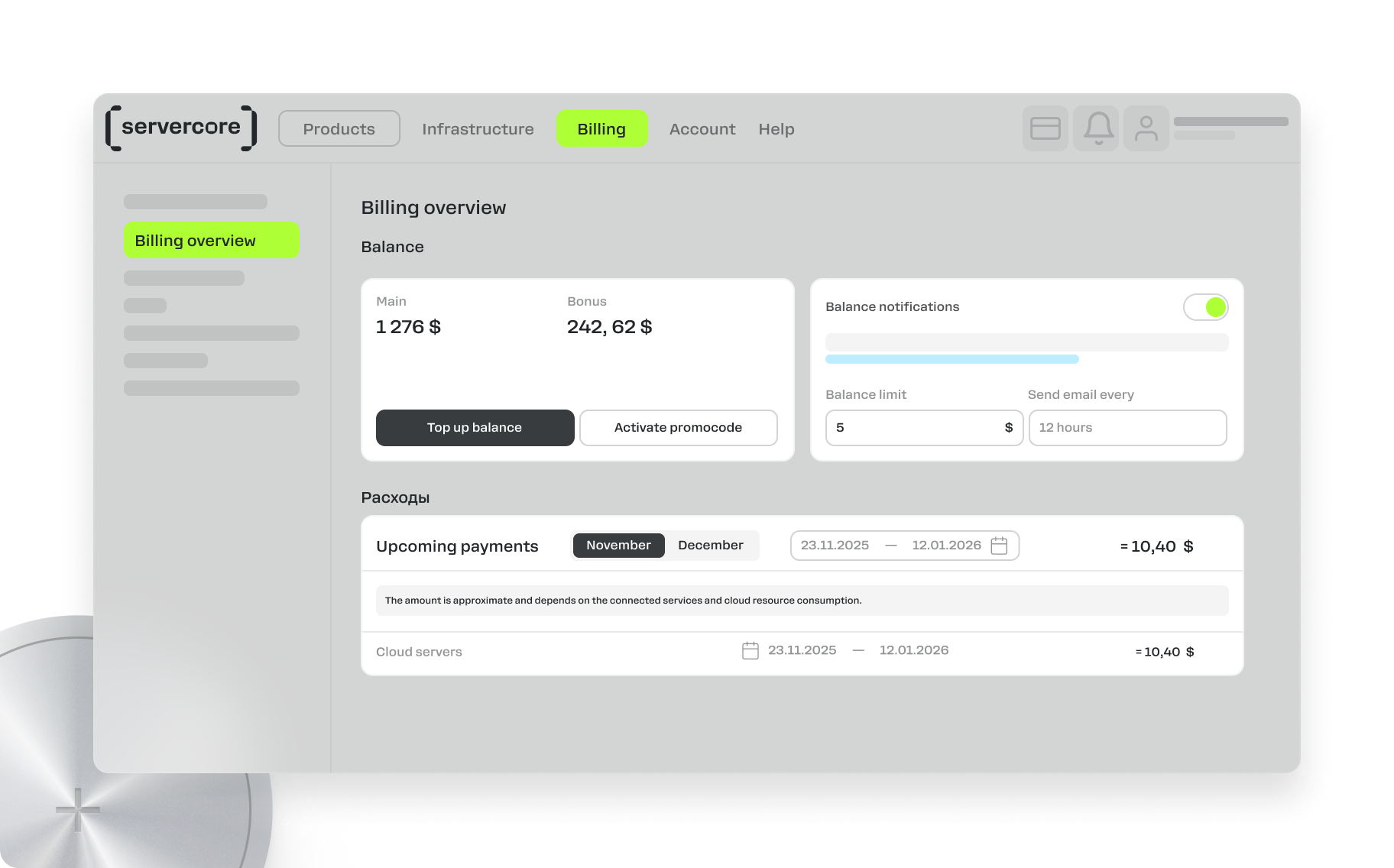
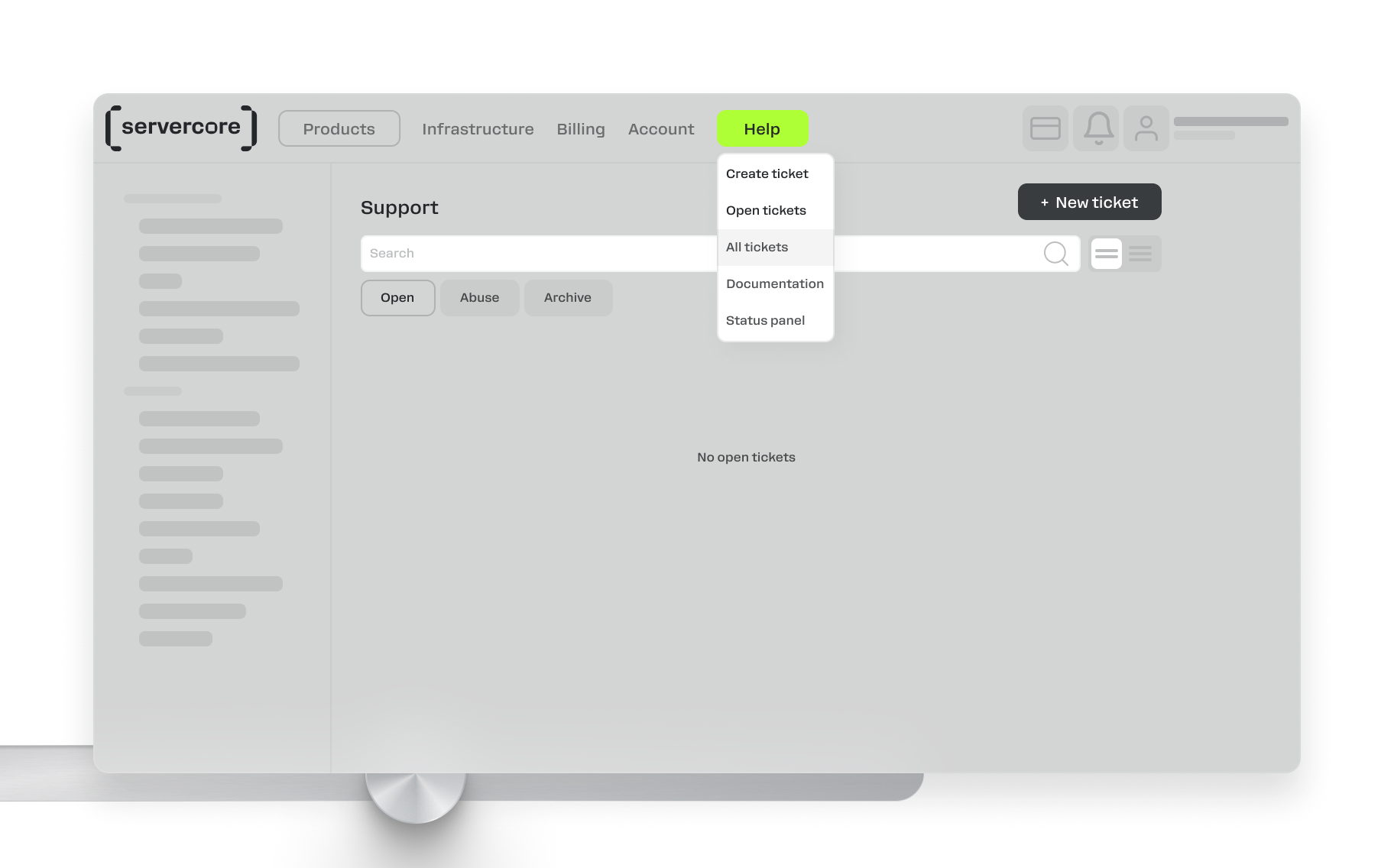
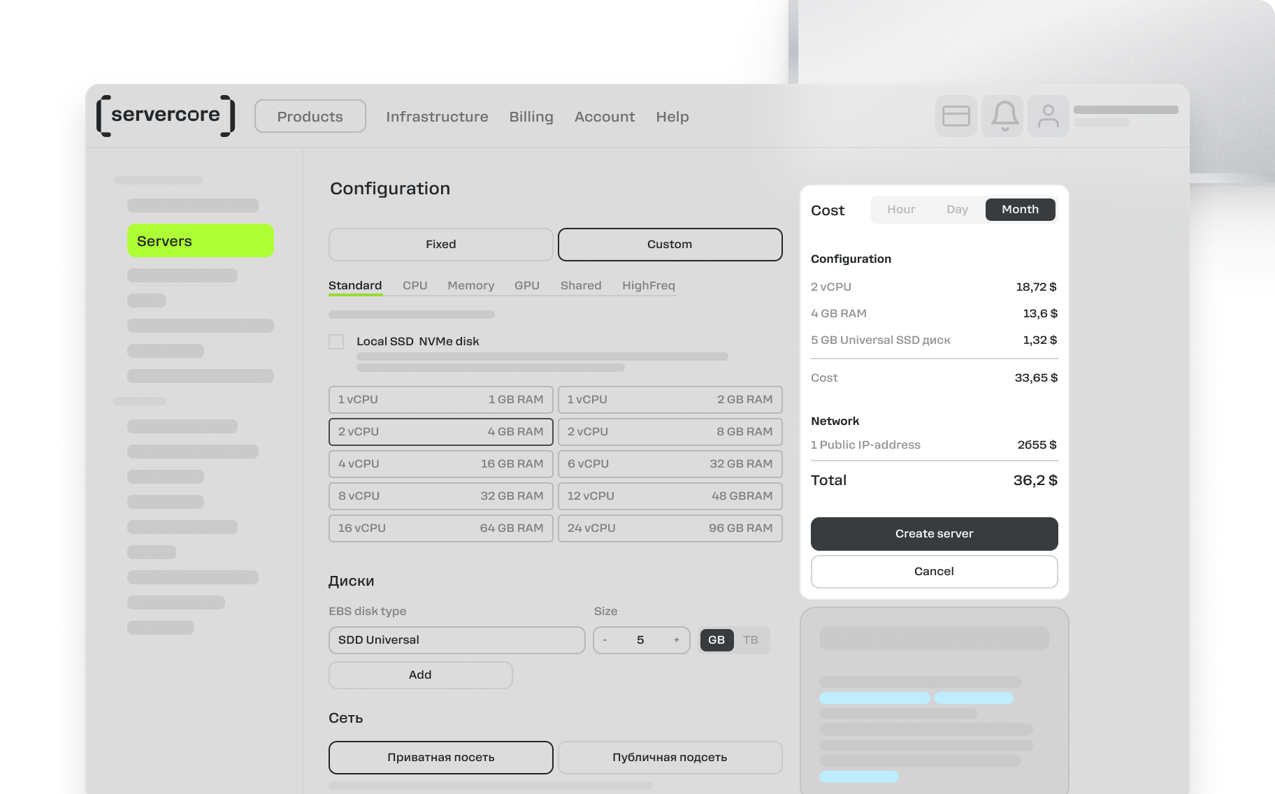
Work from User-Friendly Control Panel